DueVGA
Arduino Due VGA and TV library
Building the circuit on a breadboard
Monochrome modes require just 3 resistors. Colour needs 10 resistors. Values are as follows:
| Resistor | Quantity | |
| Both modes | 82Ω | 2 |
| Monochrome | 100Ω | 1 |
| Colour | 2.2kΩ | 2 |
| 1kΩ | 2 | |
| 820Ω | 1 | |
| 470Ω | 2 | |
| 390Ω | 1 |
(If you have 2kΩ or 510Ω
resistors you may use these instead of 2.2kΩ
and 470Ω for more accurate colour)
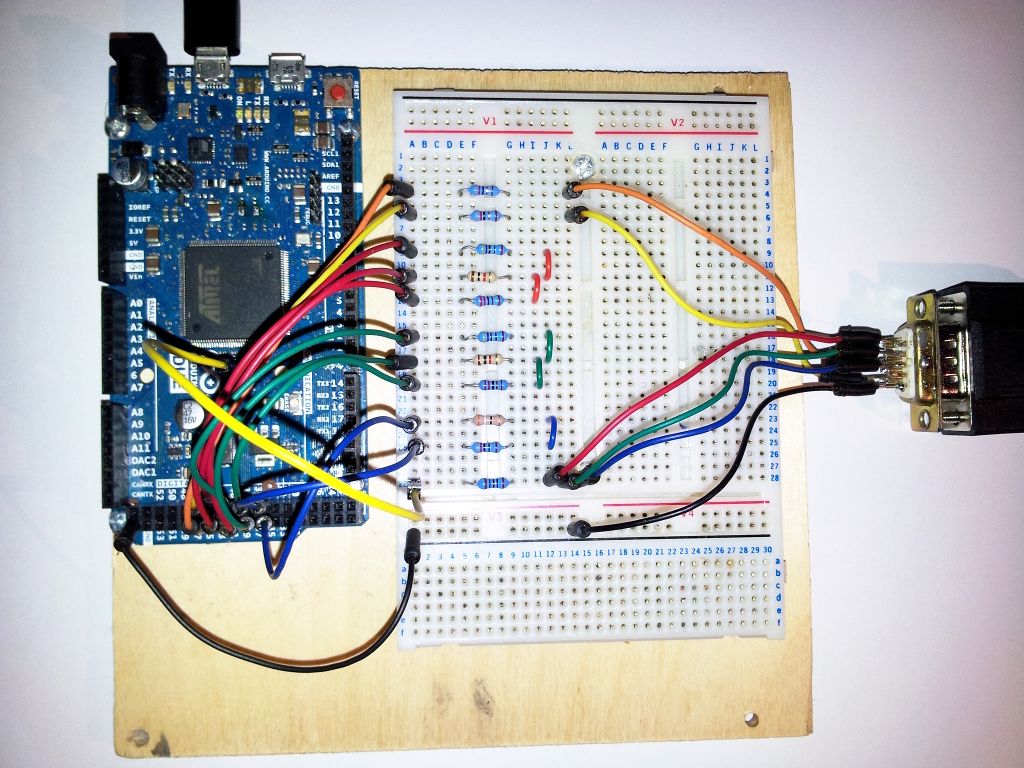
This picture shows how to wire everything up:
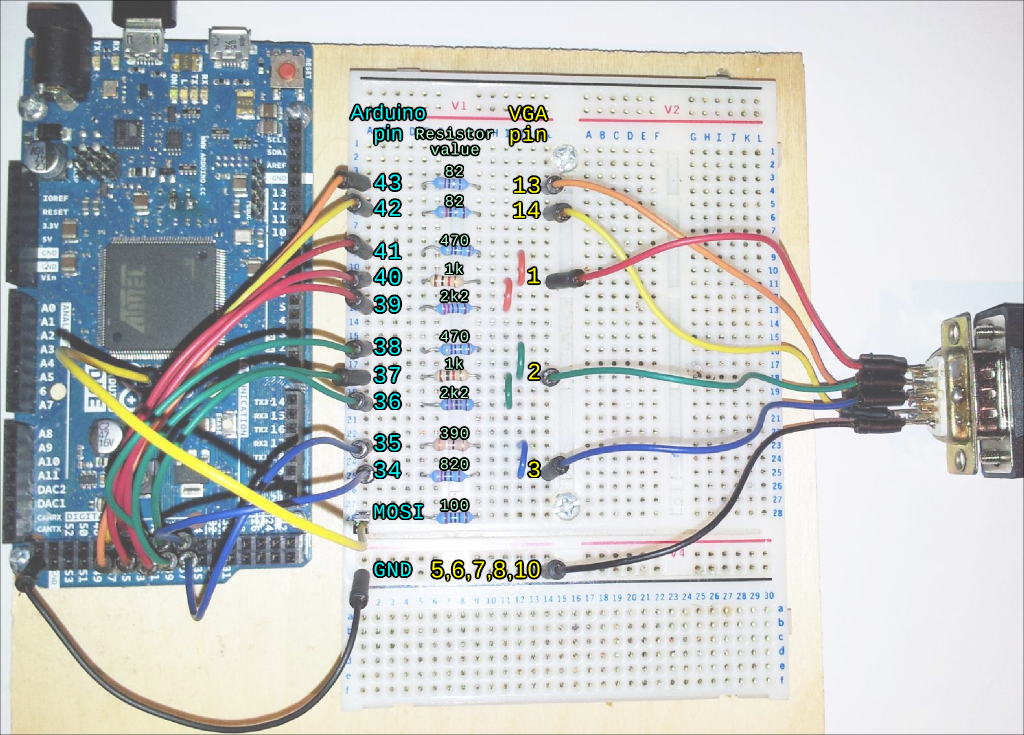
The MOSI pin is the bottom-centre pin of the 6-pin SPI connector just below the SAM3X chip - this and the 100 ohm resistor is only needed for monochrome modes. Similarly the connections to pins 34-41 and corresponding resistors are only needed for colour modes.
The above picture has the VGA socket wired for colour modes. For monochrome modes, connect the VGA RGB wires to the 100 ohm resistor as below:
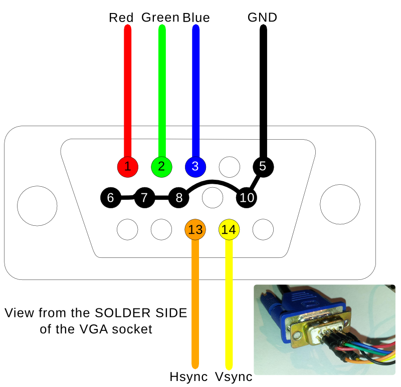
VGA socket wiring